5 Critical Factors That Determine If an X-Ray Tube Can Handle 180 kV
As an engineer with over a decade of experience in X-ray technology1, I've designed and tested numerous tubes, including some operating at high voltages. This hands-on experience, from prototyping to troubleshooting, gives me a unique perspective on the intricacies of high-voltage X-ray tube operation. My expertise, honed through countless hours in the lab and field, allows me to provide an informed and practical perspective on this topic. The short answer to whether an X-ray tube can handle 180 kV is: it depends on the design.
Achieving stable and reliable operation at 180 kV is no small feat. It requires careful consideration of several interconnected factors. The following is a ranked discussion of these factors, based on their impact on the tube's ability to withstand high voltage and maintain consistent performance, along with the engineering challenges involved in mitigating potential failure modes:
| Rank | Factor | Description | Why It Matters for High Voltage (e.g., 180 kV) |
|---|---|---|---|
| 1 | Insulation and Vacuum Quality | The tube's glass/metal envelope and internal vacuum must withstand high potential differences without breakdown. | At 180 kV, arcing risks increase dramatically; poor vacuum leads to ion bombardment and failure. Tubes use oil baths or beryllium windows for insulation, reducing external field stress. |
| 2 | Anode Heat Dissipation and Cooling | Anode materials (e.g., tungsten) and cooling systems (rotating anode, oil immersion) manage heat from electron impacts. | Power (voltage × current) rises quadratically with voltage; at 180 kV, heat can melt the anode without rotation speeds up to 10,000 rpm or advanced cooling. Sophisticated cooling loops and high-conductivity materials are essential. |
| 3 | Power Supply Stability and Ripple | Consistent DC voltage from the generator, with low ripple (fluctuations). | High ripple at 180 kV reduces average energy and increases soft X-rays; constant potential supplies are essential for efficiency and to avoid tube stress. Active filtering networks and feedback control are implemented. |
| 4 | Anode-Cathode Spacing and Geometry | Distance between electrodes and focal spot size. | Larger spacing prevents arcing but reduces efficiency; at high voltages, electron acceleration demands precise geometry to control beam focus and minimize wear. Field shaping electrodes are used. |
| 5 | Filament Current and Cathode Emission | Thermionic emission from heated tungsten filament. | High voltage pulls more electrons, but excessive draw burns out the filament; limits max current (e.g., 2–12 mA) at 180 kV to avoid overload. Filament temperature control is critical. |
1. Insulation and Vacuum Quality: The Foundation of High-Voltage Operation
The integrity of the tube's insulation and vacuum is paramount. Without robust insulation and a near-perfect vacuum, achieving stable operation at 180 kV is simply impossible. At 180 kV, even the slightest imperfection or trace amount of gas can lead to catastrophic arcing, quickly destroying the tube. The vacuum environment within the tube must be exceptionally high – typically in the range of 10-7 to 10-9 Torr – to prevent ionization of residual gas molecules. Ionization leads to a cascade effect, with ionized particles accelerating in the electric field and colliding with the anode, cathode, or tube walls, releasing more particles and ultimately causing a breakdown.
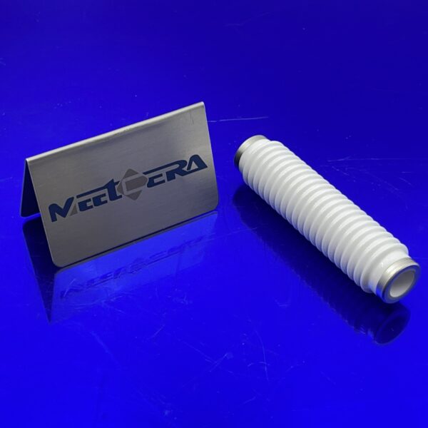
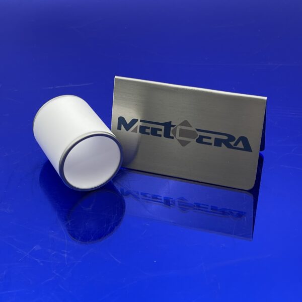
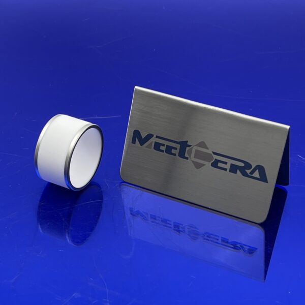
Therefore, high-voltage tubes often employ specialized glass or ceramic envelopes designed to withstand the intense electrical stress. These materials possess high dielectric strength2.

2. Anode Heat Dissipation and Cooling: Managing Immense Thermal Loads
The kinetic energy of electrons accelerated to 180 kV is immense. When these high-speed electrons strike the anode, most of their kinetic energy is converted into heat – in fact, over 99% of the electron beam energy becomes heat, with only a tiny fraction converted to X-rays. At these high voltages, the heat load intensifies dramatically, to the point where the anode can rapidly melt if the heat is not efficiently removed. Tungsten, with its exceptionally high melting point (3422 °C), is almost universally used as the anode material. But even with tungsten's resilience, sophisticated cooling mechanisms are essential.
3. Power Supply Stability and Ripple: Ensuring Consistent Performance
A stable and ripple-free power supply is absolutely crucial for consistent X-ray production at 180 kV. Voltage ripple, which refers to unwanted variations in the instantaneous voltage, introduces fluctuations in the X-ray energy spectrum. This leads to inconsistent penetration and image quality, making it difficult to obtain reliable diagnostic information or to control the dose delivered in radiotherapy applications. High ripple also increases the production of "soft" X-rays (low-energy photons), which contribute to patient dose without providing any diagnostic benefit, as they are primarily absorbed by the skin.
4. Anode-Cathode Spacing and Geometry: Balancing Efficiency and Safety
The distance between the anode and cathode, and the overall geometry of the tube's internal components, play a significant role in its high-voltage capabilities and performance. Closer spacing between the anode and cathode can increase the efficiency of X-ray production, as the electrons have a shorter distance to travel and are less likely to collide with residual gas molecules. However, closer spacing dramatically increases the risk of arcing and electrical breakdown. At 180 kV, a precise balance must be struck to optimize efficiency while maintaining a sufficient safety margin against arcing.
5. Filament Current and Cathode Emission: Controlling the Electron Flow
The filament current directly controls the temperature of the tungsten filament in the cathode. This temperature, in turn, determines the rate of thermionic emission – the process by which electrons are emitted from the heated filament. Higher filament currents cause the filament to heat up to higher temperatures, resulting in a greater number of electrons being emitted. This increases the X-ray tube current and, consequently, the X-ray output intensity. However, excessive filament current can lead to premature filament burnout, reducing the tube's lifespan and potentially causing catastrophic failure.
Conclusion
In conclusion, while operating an X-ray tube at 180 kV is indeed possible and essential in many specialized applications, it requires careful attention to a complex range of interacting factors. It's not simply a matter of applying high voltage; it's a sophisticated engineering challenge involving insulation, vacuum quality, heat dissipation, power supply stability, electrode geometry, and filament control. A deep understanding of these factors is crucial for designing, operating, and maintaining high-voltage X-ray systems safely and reliably.


No comment