Ceramic Insulator Brazing: 20–100kV+ Withstand Design
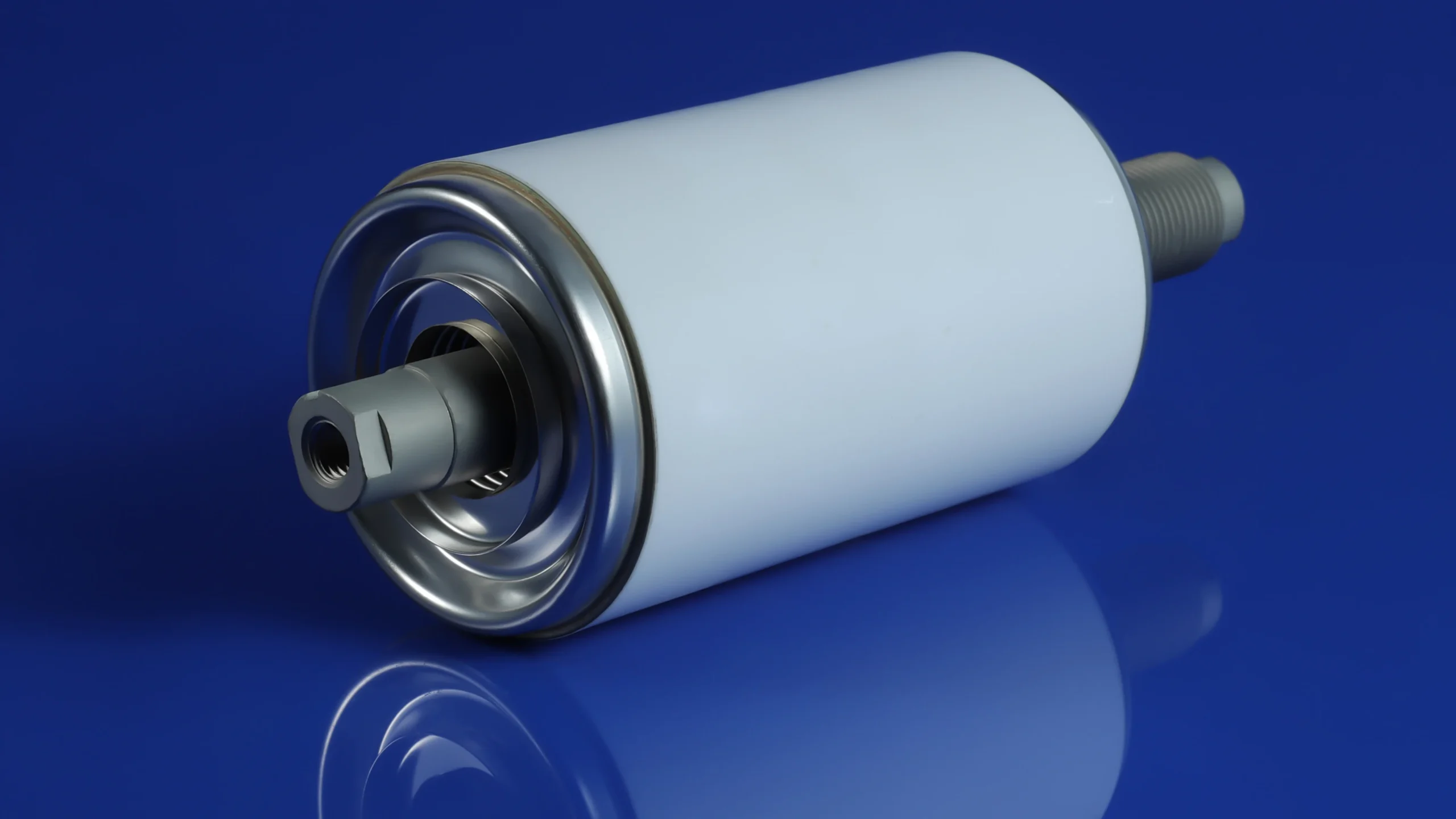
High-voltage ceramic insulators (feedthroughs) are vital for vacuum systems, particle accelerators, medical X-ray, high-voltage power, and semiconductor applications, needing reliable insulation and hermetic sealing at 20kV–100kV+. Brazing is the key ceramic-to-metal joining process that determines withstand voltage and durability.
Main challenges: CTE mismatch between alumina and metals, electrical breakdown, and brazing residual stress. Leading products (e.g., Meetcera, Morgan) achieve 70–100kV+ via material matching, geometry optimization, and surface strengthening. This article covers these core design strategies for engineers.
1.Three Core Challenges in High-Voltage Ceramic Brazing
High-voltage ceramic brazing faces three primary failure modes:
(1). Electrical Breakdown Mechanisms: Including bulk breakdown, surface flashover, and triple-point localized electric field concentration discharge. In high vacuum or SF₆ environments, surface flashover is often the limiting factor; actual withstand voltage is far below the theoretical bulk strength of alumina ceramics (20–30 kV/mm or higher, but surface flashover only a few kV/mm).
(2). Interface Microcracks Caused by CTE Mismatch: Alumina CTE ≈ 6.5–8.0 × 10⁻⁶/°C, while common metals (e.g., stainless steel or copper) reach 16–18 × 10⁻⁶/°C. Greater metal contraction during cooling induces tensile/compressive stress on the ceramic side, forming microcracks that propagate and cause failure.
(3). Residual Stress During Brazing Thermal Cycling: Brazing temperatures of 800–1000°C generate residual stresses of hundreds of MPa (peak values often >200–300 MPa), reducing mechanical strength and amplifying electric field distortion, thereby promoting discharge.
These challenges are interconnected: CTE mismatch drives residual stress, which worsens surface electric field distribution and ultimately limits withstand voltage. Design must therefore form a closed loop from source-level CTE matching to end-level surface strengthening.
2.CTE Matching Strategy
CTE matching is the first line of defense, achieved by selecting alloys with CTE close to ceramics for “co-expansion.”
Mainstream sealing metal comparison (typical average CTE from 20–450°C, unit: 10⁻⁶/°C):
| Material | Typical CTE (×10⁻⁶/°C) | Main Advantages | Disadvantages & Trade-offs | Typical Voltage Range |
|---|---|---|---|---|
| Kovar (4J29, Fe-29Ni-17Co) | 5.0–6.0 | Excellent match with alumina, good machinability, moderate cost | Slight magnetism | 20–70kV (classic mainstream) |
| Alloy 42 (Fe-42Ni) | 4.4–5.5 | Cost-effective alternative, low CTE | Stronger magnetism, moderate strength | 20–60kV (high cost-performance) |
| Invar (4J36, Fe-36Ni) | 1.5–2.0 | Ultra-low CTE, suitable for severe temperature variation or extreme HV | Difficult processing, high cost, brittle | Special high/low temperature cycles |
| Pure Mo / Mo Alloys | 5.0–6.0 | Superior match, high strength, heat resistant | High brittleness, difficult welding, higher cost | 100kV+ extreme applications |
Kovar offers the best balance (Ceramaseal 100kV feedthroughs typically use Kovar + alumina); Mo is suited for ultimate withstand voltage but requires complex buffering; Invar is used for special thermal cycling scenarios.
For example, in a 100kV alumina feedthrough, Kovar keeps residual stress low, while switching to Mo can increase withstand voltage by 10–20%.
3.Joint Geometry Optimization and Surface Strengthening
Even with good CTE matching, residual stress and electric field concentration must be further suppressed through geometry and surface methods—this is the core of commercial high-voltage feedthrough competitiveness.
(1)Geometry Optimization (reducing stress concentration and field peaks):
- Traditional flat joint defects: Sharp edges cause triple-point electric field peaks + stress concentration, prone to flashover.
- Mainstream solutions: Conical transition (most recommended, cone angle 10°–30°, disperses stress 30–50% and extends creepage distance); stepped/multi-level structure (graded buffering); flexible buffer layer/gradient transition (absorbs deformation); braze thickness control (50–100 μm).
(2)Surface Treatment and Insulation Strengthening (suppressing surface flashover):
- High-precision polishing (Ra < 0.1 μm, increases breakdown voltage 20–40% by reducing field distortion and adsorbed gases).
- Glazing/vitrification coating (shields triple point, increases surface resistivity, enhances hydrophobicity; commercial standard, used by Kyocera, Ceramaseal, etc.).
- Auxiliary measures: Edge filleting (R > 1 mm), shielding electrodes/grading rings (uniform electric field).
Synergistic Effect: The optimal combination is “conical geometry + glazed surface,” which can elevate withstand voltage from a basic 30–50 kV to 100 kV+, with improvements of 50% or more.
4.Withstand Voltage Testing Standards
Testing Standards and Methods: IEC 60168, GB/T 775, ASTM, etc.; includes power-frequency AC, DC, lightning impulse; gradual voltage ramp in vacuum/SF₆, recording 1-min withstand and breakdown voltages.
Typical Measured Data (alumina ceramic feedthrough reference values):
- Flat joint + Kovar: Breakdown ≈ 30–50 kV.
- Conical + glazing + Kovar: 70–100 kV DC stable.
- Mo alloy + optimized geometry: 100–125 kV (some corona-free designs).
Commercial Benchmarks: Ceramaseal high-voltage feedthroughs (70–125 kV DC, some corona-free up to 180 kV) use conical transition + buffer + glazing; Morgan emphasizes stepped/flexible layers + surface strengthening, suitable for 20–100 kV RF/water-cooled applications.
Best practice: Kovar/Mo matching + conical geometry + glazing + electric field simulation verification.
5.Conclusion
To achieve 20kV–100kV+ withstand voltage in high-voltage ceramic insulator brazing, follow this core path: prioritize CTE matching (Kovar/Mo preferred) → conical geometry + glazing → rigorous voltage testing. Key bottlenecks are long-term stability at extreme voltages and cost. Future advances include active brazes, graded materials, and AI optimization. Start with Kovar + alumina, require conical + glazing, and use early FEA simulation for efficient, reliable designs.