TWT Ceramic Feedthrough Brazing: Multi-Pin Multi-Layer Guide
Traveling wave tubes (TWT) serve as core amplifiers in satellite communication and radar systems, where ceramic feedthrough components directly impact signal transmission and vacuum seal reliability. As the second article in this series, this piece focuses on dissecting the multi-pin/multi-layer brazing technology for traveling wave tube ceramic feedthroughs, combined with practical process flows for ceramic brazing in vacuum electron devices, providing engineers with actionable technical guidance.
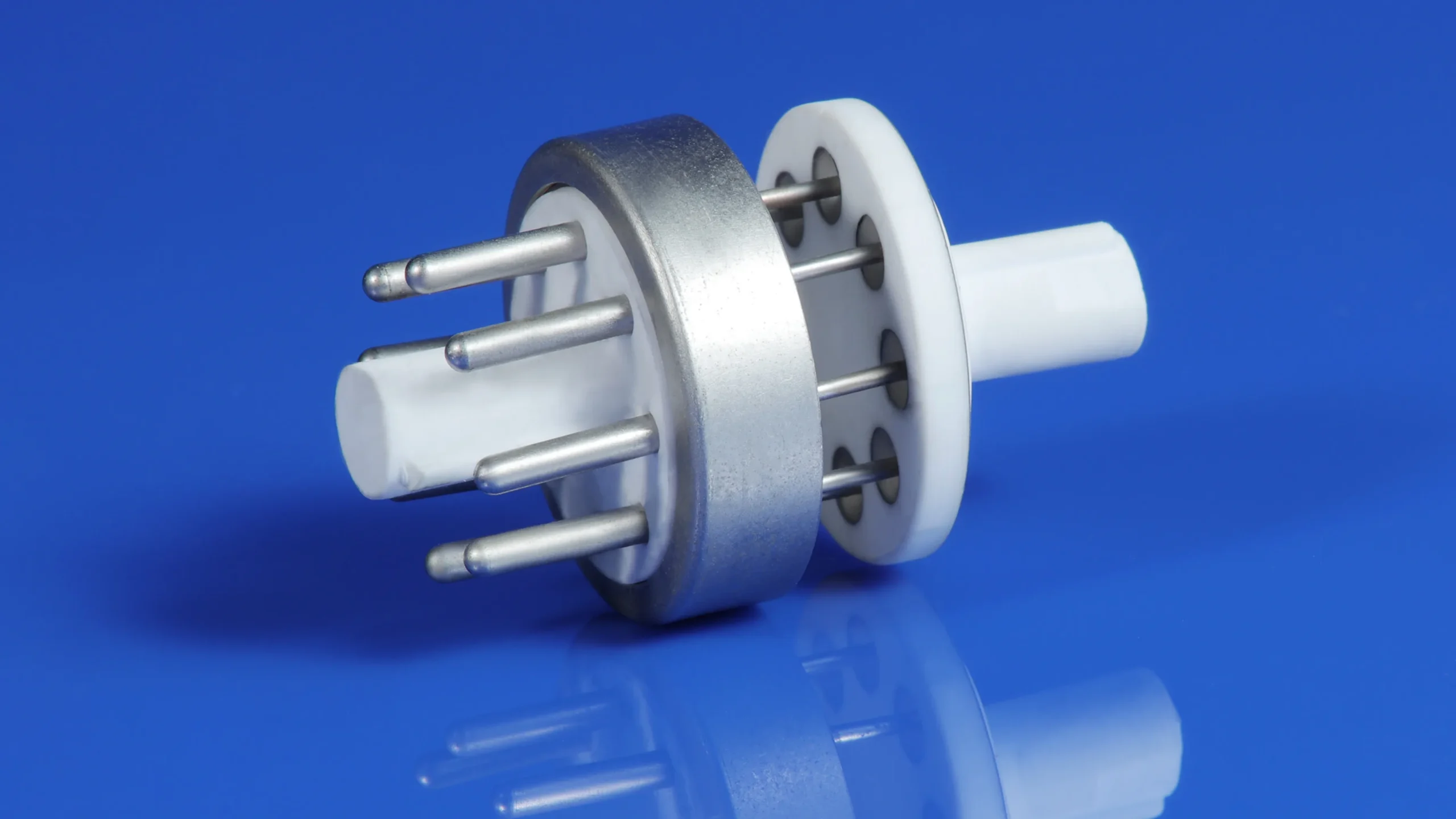
1. Types of Feedthrough Structures and Design Principles
Common feedthroughs include single-pin, multi-pin, and multi-layer ceramic feedthroughs:
- Single-pin feedthrough: Simple structure, used for low-complexity signal transmission
- Multi-pin feedthrough: Supports synchronous multi-channel signals, widely used in TWT electron guns and collectors
- Multi-layer ceramic feedthrough: Enables high-density interconnects, suitable for complex RF circuits
Hermetic multi-pin feedthroughs are essential for providing instrumentation signals, voltage, and current into high-vacuum environments while maintaining electrical isolation.
2. Typical Process Flow for Traveling Wave Tube Ceramic Feedthroughs:
- Ceramic surface metallization (Mo-Mn method or active metal method)
- Precision alignment assembly
- Vacuum brazing (Ag-Cu-Ti active filler metal, vacuum level 10⁻⁴~10⁻⁶ Pa)
- Heat treatment and stress relief
- Non-destructive testing (X-ray, helium leak detection, electrical performance testing)
Active metal brazing (AMB) simplifies the process by enabling direct brazing to raw ceramics in vacuum, using titanium-containing alloys to achieve strong hermetic bonds without prior metallization.
3. Process Challenges and Solutions for Multi-Layer Feedthroughs
- Alignment accuracy: Error must be controlled within ±0.05 mm, using laser assistance or fixture positioning
- Residual stress control: Optimize temperature profiles via gradient interlayers or finite element simulation
- Inter-layer insulation and hermeticity: Strictly control metallization layer thickness and interface reactions
Advanced techniques include active metal brazing (AMB) and multi-step brazing compatibility processes. For residual stress management in ceramic-metal assemblies (including multi-layer designs), finite element simulations help predict and mitigate thermal mismatch effects, as demonstrated in related ceramic substrate studies.
Key Quality Control Points:
- Thermal cycling test (-55°C~+125°C, hundreds of cycles)
- High-voltage withstand testing and RF performance verification
- X-ray inspection for internal defects
4 Conclusion
Multi-pin/multi-layer feedthrough brazing is one of the difficulties in high-frequency ceramic brazing. Mastering these processes can significantly improve TWT reliability. The next article will focus on low-loss metallization and brazing process optimization to help you further reduce RF losses.
FAQ
Q. What is the typical alignment accuracy requirement for multi-pin feedthroughs in traveling wave tubes?
Error must be controlled within ±0.05 mm, usually achieved with laser assistance or high-precision fixtures.
Q. What is the most common failure mode in multi-layer ceramic feedthroughs?
The most common is micro-cracks or interface debonding caused by inter-layer residual stress, which requires temperature profile optimization and interlayers for mitigation.
Q. What advantages does active metal brazing (AMB) have over the traditional Mo-Mn method?
AMB enables direct brazing of aluminum nitride, with stronger interface bonding, thinner metal layers, and lower RF loss.