Why X-Ray Tube Insulation Fails: 8 Common Causes Explained
As a seasoned engineer with over 15 years of experience in X-ray tube design and manufacturing, I've witnessed firsthand the critical role that high-voltage insulation plays in the overall reliability and performance of these complex devices. My expertise stems from extensive research, hands-on experience in troubleshooting field failures, and a deep understanding of material science principles applied to X-ray technology. I've led teams responsible for designing and testing insulation systems for both medical and industrial X-ray tubes. In this article, I'm leveraging that experience to break down the top 8 reasons why X-ray tube insulation fails.
| Rank | Cause | Approximate % of Insulation-Related Failures* | Typical Tube Age When It Occurs | Notes |
|---|---|---|---|---|
| 1 | Tungsten vapor deposition1 on envelope | 30–40% | Mid-to-late life (>500k–1M exposures) | Primary “wear-out” mechanism in glass and metal-ceramic tubes. This deposition gradually reduces surface insulation and increases the risk of high-voltage breakdown. |
| 2 | Dielectric oil degradation2/contamination | 20–25% | Any age, accelerates after 3–5 years | Moisture, carbonization from prior arcs, sludge. These contaminants reduce the oil's dielectric strength, leading to increased arcing potential and compromised insulation. |
| 3 | Loss of vacuum3 (slow leaks/outgassing) | 15–20% | Usually mid-life onward | Catastrophic when it finally arcs. Even small leaks can accumulate over time, eventually leading to a significant reduction in vacuum, which drastically lowers the breakdown voltage. |
| 4 | Excessive heat / thermal runaway4 | 10–15% | Early to mid-life if abused | Often operator-related (no cool-downs, overuse). Overheating can lead to rapid insulation degradation, accelerated tungsten evaporation, and premature failure of the X-ray tube. |
| 5 | Field emission & spurious electron emission5 | 5–10% | Any age, worse in aged tubes | Micro-protrusions on cathode/anode. These emissions can cause localized heating and damage to the insulation, particularly in areas of high electric field concentration. |
| 6 | Particulate contamination6 inside insert | 5–8% | Usually early life or after repair | Manufacturing residue or rotor debris. These particles can become charged and move under the influence of the high electric field, leading to micro-arcs and insulation breakdown. |
| 7 | Mechanical/aging damage to insulators7 | 3–6% | Late life | Cracks, crazing from thermal cycling. Repeated thermal stress can cause microscopic cracks and crazing in the ceramic insulators, weakening their dielectric properties and increasing the risk of failure. |
| 8 | Overvoltage or bad HV cable8/receptacle | 2–5% | Any age | Often installation or cable maintenance issue. Voltage spikes or faulty connections can cause immediate and catastrophic damage to the insulation, leading to rapid tube failure. |
1. Tungsten Vapor Deposition on the Envelope (30–40%)
Why It Happens
- Tungsten evaporates from the anode during high-temperature operation, a natural consequence of the high power densities involved. The amount of evaporation increases with anode temperature and exposure time.
- Vapor gradually deposits on the ceramic or glass envelope, forming a thin, conductive film. This process is exacerbated by poor vacuum conditions and inadequate anode cooling.
- Creates a darkened conductive path, bridging high-voltage insulation gaps. The dark film reduces the surface resistivity of the envelope.
- Reduces the surface insulation strength, increasing the likelihood of electrical breakdown. As the tungsten film thickens, the breakdown voltage decreases.
Effects
- Increased leakage current, which can lead to instability and inaccurate measurements.
- Lower dielectric withstand voltage, making the tube more susceptible to arcing at lower operating voltages.
- Eventual flashover or internal arc, resulting in catastrophic failure of the X-ray tube.
Typical Tube Age
Mid-to-late life: >500k–1M exposures. This is often the primary "wear-out" mechanism for most X-ray tubes.
Engineering & Prevention
- Polished, low-porosity ceramic insulators: These materials reduce tungsten adhesion and improve surface insulation.
- Optimized anode heat dissipation: Efficient cooling reduces the anode temperature and minimizes tungsten evaporation.
- Controlled cool-down cycles: Gradual cooling reduces thermal stress and prevents shock that encourages tungsten evaporation.
- Regular tube monitoring: Monitoring for increased leakage current and changes in voltage withstand can provide early warning of tungsten deposition issues.
2. Dielectric Oil Degradation or Contamination (20–25%)
Why It Happens
Dielectric oil degrades due to:
- Moisture absorption, which lowers the dielectric strength and increases conductivity.
- Carbonization from previous arcs, creating conductive particles that further reduce insulation.
- Sludge formation, a byproduct of oil breakdown that collects on surfaces and inhibits heat transfer.
- High-temperature operation, which accelerates the degradation process.
Effects
- Lower dielectric strength, meaning the oil can withstand less voltage before breaking down.
- Increased likelihood of arcing, especially near areas of contamination or high electric field concentration.
- Chemical breakdown of insulation oil, leading to the formation of corrosive byproducts that can damage other components.
Tube Age
Any age, with rapid degradation after 3–5 years. The rate of degradation depends on operating conditions and environmental factors.
Prevention
- Oil sampling & periodic replacement: Regular testing and replacement of the dielectric oil can prevent significant degradation.
- Control moisture migration: Use sealed housings and desiccants to prevent moisture from entering the oil.
- Use sealed ceramic components: Prevent ingress of contaminants into the oil from the components, prolonging its life.
- Regularly inspect for leaks and seals: Maintaining seal integrity minimizes oil loss and prevents contaminant ingress
3. Loss of Vacuum (15–20%)
Mechanism
- Slow leaks at ceramic-to-metal joints: These joints are susceptible to micro-cracks and degradation over time.
- Outgassing from low-density ceramic materials: Gases trapped within the ceramic can slowly release, reducing the vacuum level.
- Seal fatigue from thermal cycling: Repeated heating and cooling can weaken seals and cause them to leak.
Consequences
- Gas ionization under HV, leading to unstable operation and increased arcing potential.
- Sudden catastrophic arc, resulting in immediate and often irreversible damage to the tube.
- Immediate tube failure, requiring replacement and system downtime.
Typical Age
Mid-life onward. The rate of vacuum loss increases with age and thermal stress.
Prevention
- High-bond-strength metallized ceramics: These materials provide a more reliable seal and reduce the risk of leakage.
- Helium leak testing (<1×10⁻¹² Pa·m³/s): Rigorous leak testing during manufacturing ensures vacuum integrity.
- High-temperature vacuum bake-out: Removing trapped gases from materials before assembly minimizes outgassing.
- Regular vacuum level monitoring: Monitoring vacuum levels allows for early detection of leaks and preventative maintenance
4. Excessive Heat / Thermal Runaway (10–15%)
Causes
- Lack of cool-down time: Insufficient cooling between exposures allows the anode to overheat.
- Overuse in continuous high-load imaging: Repeatedly operating the tube at its maximum power rating can lead to thermal overload.
- Faulty cooling system: Malfunctioning cooling systems can prevent adequate heat dissipation.
- Anode overheating: Anode overheating can be caused by a number of factors, including high load, poor cooling, and material defects.
Effects
- Envelope insulation breakdown: Excessive heat can damage the ceramic or glass envelope, reducing its dielectric strength.
- Accelerated tungsten evaporation: High temperatures increase the rate of tungsten evaporation, leading to rapid deposition on the envelope.
- Early-life failure patterns: Thermal runaway can cause premature failure of the X-ray tube, significantly reducing its service life.
Prevention
- Enforce cool-down protocols: Implementing and adhering to proper cool-down procedures is crucial.
- Monitor real-time thermal load: Keeping track of the tube's thermal load allows for adjustments to prevent overheating.
- Improve heat dissipation design: Optimizing the cooling system improves heat management.
- Regularly inspect the cooling system: Proactively check operation of the cooling system to avoid catastrophic consequences.
5. Field Emission & Spurious Electron Emission (5–10%)
Why It Happens
- Micro-protrusions on electrodes: Small imperfections on the electrode surfaces can create localized areas of high electric field concentration.
- Roughened surfaces after long-term use: Erosion and wear can roughen the surfaces of electrodes, increasing the likelihood of field emission.
- Contaminants increasing local field intensity: Particles or impurities on the electrodes can amplify the electric field and promote electron emission.
Effects
- Uncontrolled electrons hitting the envelope: Emitted electrons can strike the envelope, causing localized heating and damage.
- Local heating & insulation degradation: Impact from stray electrons can cause insulation defects.
When It Occurs
Any age; worse in aged tubes. Electrode wear and contamination increase over time.
Mitigation
- Smoother electrode surfaces: Polishing electrodes reduces the risk of field emission from imperfections.
- Conditioning during manufacturing: A careful conditioning process during manufacturing can reduce field emissions for long term reliability.
- High-dielectric-strength ceramics: Using ceramics with high dielectric strength provide extra protection against breakdown.
6. Particulate Contamination Inside the Insert (5–8%)
Sources
- Manufacturing residues: Leftover compounds or particles can easily become trapped during processes.
- Rotor bearing debris: Wear from bearing can dislodge micro-particles.
- Ceramic machining particles: Machining can leave ceramic particles that are difficult to clean.
- Contamination from service operations: Poor handling & servicing can contaminate a clean X-ray tube interior.
Failure Mechanism
- Charged particles move under HV: Particles are charged when high-voltage is applied and move to areas of opposite charge.
- Create micro-arcs inside the envelope: As particles build, they may create paths for micro-arcs causing rapid breakdown.
Timeframe
Typically early life, unless introduced during repair. Contamination may be present early if not removed during manufacturing.
Prevention
- Clean-room-grade assembly: Proper environments prevent introducing contaminants during assembly.
- High-purity ceramic materials: Using high purity materials in construction prevents introduction of chemicals.
- Particle traps inside insert assemblies: Particle traps added internally can attract and retain contaminants.
7. Mechanical or Aging Damage to Insulators (3–6%)
Mechanism
- Thermal cycling stress: Repeat rates of thermal cycling may lead to increased material stress.
- Cracks or crazing on ceramic surfaces: Microscopic cracks can result from these continued stresses.
- Reduced dielectric strength at damaged zones: Breakdown can occur at reduced voltages from reduced material density at cracks.
Visible Signs
- Whitened or crazed ceramics: Discolored ceramics are indicators of surface damage.
- Micro-fracture patterns: High-resolution microscopy can reveal if cracking occurs.
When It Happens
Primarily late life. Repeat stresses over extended periods culminate in part breakdown.
Prevention
- 99.5%+ alumina ceramic: High purity ceramics are more durable and less prone to cracking.
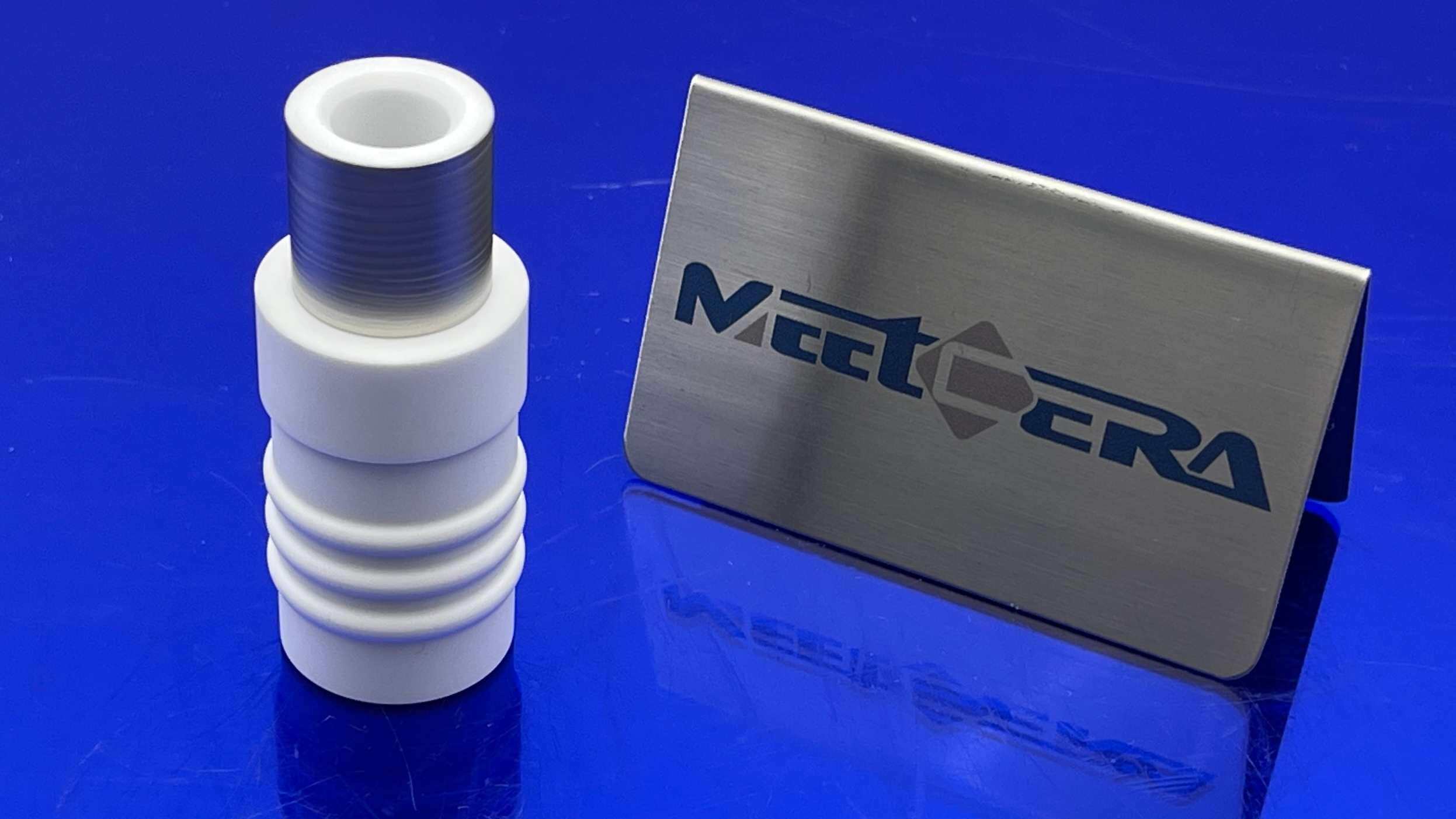
- Ribbed/wave-form insulation structures: Geometries designed to compensate for thermal expansion/contraction.
- Stronger brazing joints: Brazing using quality methods better bonds materials.
8. Overvoltage or Faulty HV Cable/Receptacle (2–5%)
Causes
- Generator voltage spikes: Unstable voltages are often caused by surges exceeding component ratings.
- Poor cable maintenance: Insulation can degrade or connectors corrode without maintenance activities.
- Loose or contaminated connectors: Inadequately cleaned or maintained connectors can arc internally.
Effects
- Flashover at cable–tube interface: Sudden overvoltage can readily cause flashover at connections.
- External insulation degradation: Continuous use with HV faults leads degrades connector insulation.
When It Occurs
Any age. Voltage abuse with poor maintenance leads to rapid breakdowns.
Prevention
- Routine HV cable replacements: Cables replaced on schedules avoid maintenance issues.
- Cleaning and reseating connectors: Connectors need cleaned to avoid corrosion and arcing.
- High-quality ceramic feedthroughs: Quality feedthroughs protect against breakdowns.
Looking to Improve X-Ray Tube Insulation Reliability? We Can Help.
If your application requires high-voltage ceramic components, metallized ceramic tubes, or custom insulation structures for X-ray systems, our engineering team can support your design with.
Ready to upgrade your X-ray insulation components?
👉Contact our engineering team for a quote or technical consultation today.
-
Explore the mechanisms behind tungsten vapor deposition to prevent insulation failures in X-ray tubes. ↩
-
Learn about the impact of oil degradation on insulation and overall tube reliability. ↩
-
Understanding vacuum loss can help in maintaining optimal performance and preventing failures. ↩
-
Discover how to manage thermal issues to extend the life of X-ray tubes. ↩
-
Gain insights into how field emissions can lead to insulation breakdown in X-ray systems. ↩
-
Learn about contamination sources and their impact on insulation reliability. ↩
-
Identifying mechanical damage early can prevent costly failures in X-ray tubes. ↩
-
Understanding overvoltage risks can help in implementing better maintenance practices. ↩


