2026 Vacuum Ceramic Feedthrough Selection Guide
Vacuum ceramic feedthroughs are essential components in vacuum systems for transmitting electrical signals and power while providing insulation and maintaining hermetic sealing under high or ultra-high vacuum conditions. In 2026, with rapid advancements in semiconductor processing, particle accelerators, vacuum coating, and space simulation, demands for higher voltage, current capacity, and leak-tightness have increased significantly. Improper selection can lead to leaks, dielectric breakdown, or system failure. This article focuses on KF40 and ISO flange-type ceramic feedthroughs, detailing flange characteristics, high-voltage parameters, and gas-tightness testing standards to help engineers select reliably and ensure optimal system performance.
1.Vacuum Ceramic Feedthrough Basics
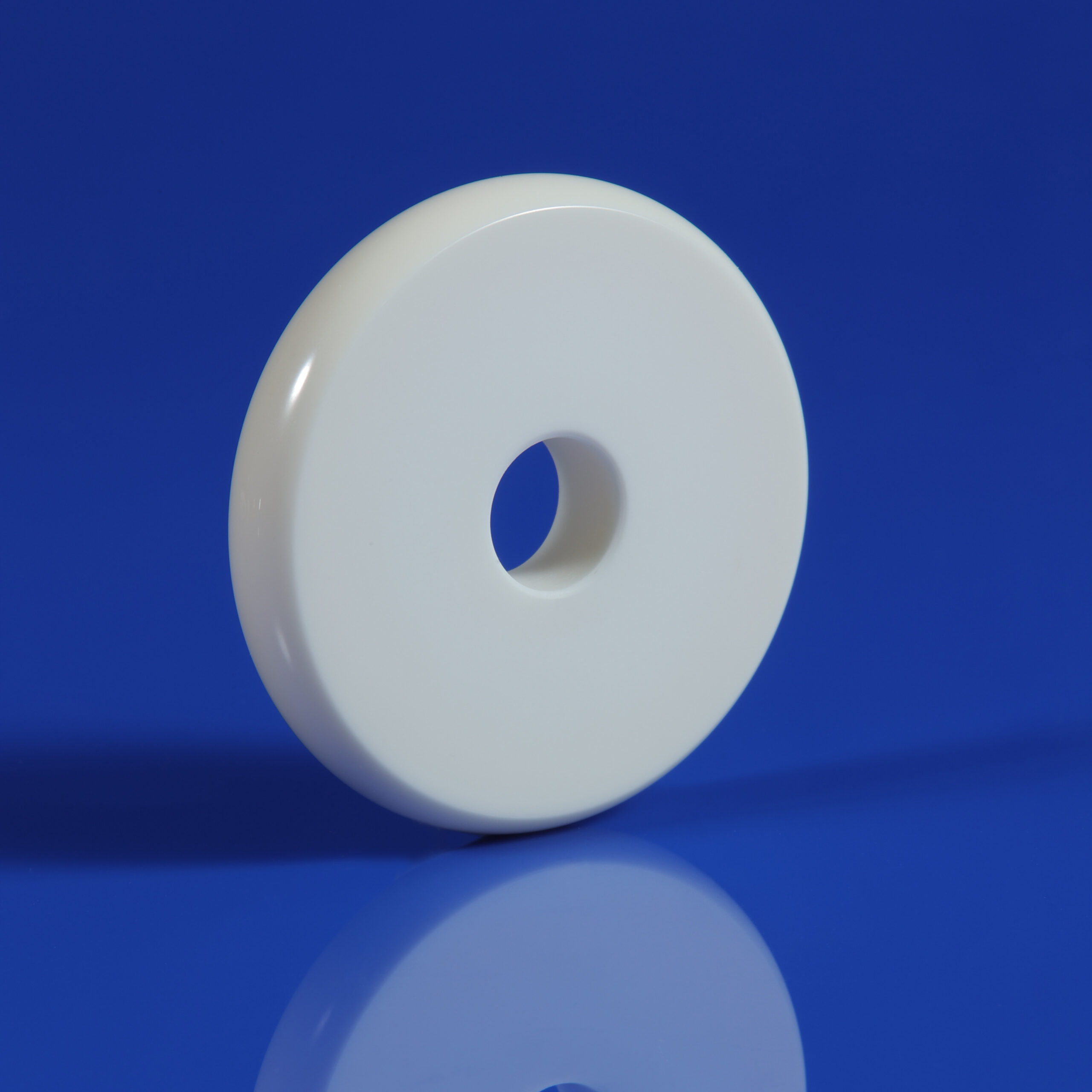
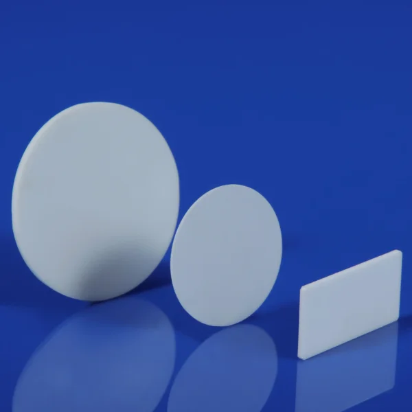
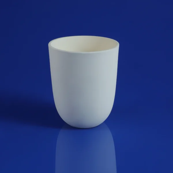
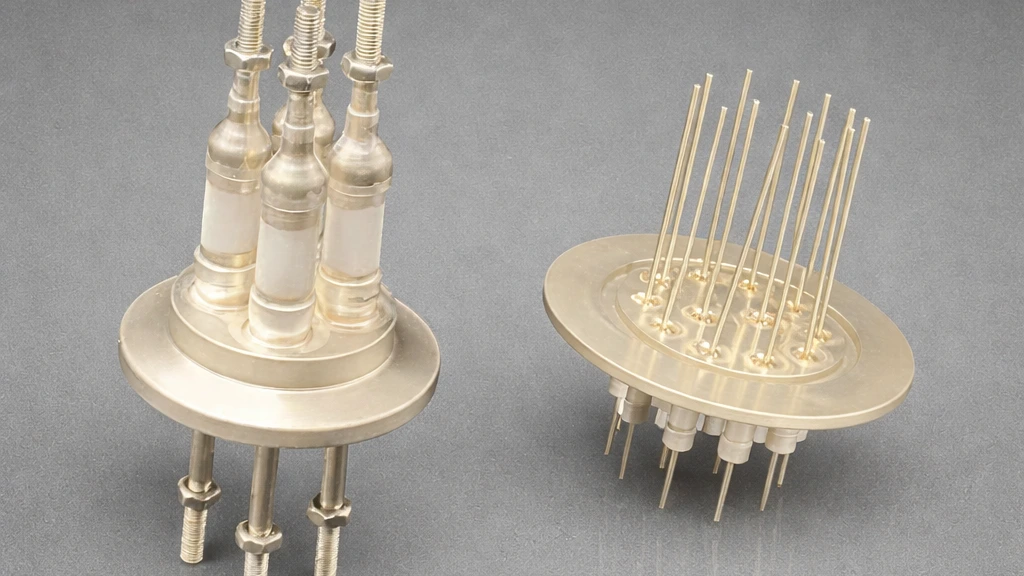
Vacuum ceramic feedthroughs use a ceramic-to-metal sealed structure with high-purity alumina (Al₂O₃) insulation to enable electrical connections from atmosphere to vacuum side while preserving hermeticity. Main types include high-voltage, RF, multi-pin signal, and thermocouple/instrument feedthroughs. Ceramic offers outstanding advantages: high dielectric strength (>400 V/mil), wide temperature range (-269°C to 450°C), low outgassing, and corrosion resistance. Compared to glass-metal types, ceramic feedthroughs are better suited for ultra-high vacuum (UHV) applications.
2.Flange Selection Details: KF40 vs. ISO Flanges
KF40 and ISO Flange Comparison Table
| Item | KF40 (NW40/ISO-KF DN40) | ISO Flange (ISO-K/ISO-F) | Comparison with CF Flange |
|---|---|---|---|
| Sealing Method | Quick-clamp with O-ring + centering ring | Clamp or bolted | KF/ISO: O-ring; CF: Copper gasket knife-edge |
| Installation Ease | Very high, quick assembly/disassembly | Moderate | CF is the most difficult |
| Applicable Vacuum Level | High vacuum to UHV (~10⁻⁸ Torr or better) | High vacuum to UHV | CF is best (UHV+) |
| Bakeout Temperature Limit | ≤205°C (limited by O-ring) | Similar to KF or slightly higher | CF up to 450°C+ |
| Mechanical Strength | Moderate | Higher | CF is the highest |
| Cost & Applications | Low cost; labs and small/medium equipment | Moderate; large systems | High; premium UHV |
| Recommended O-ring | Viton (standard) / Kalrez (corrosion-resistant) | Same as left | – |
KF40 offers excellent convenience and compatibility; ISO flanges provide greater mechanical strength for demanding setups. The 2026 trend emphasizes modular designs and mirror-polished surfaces to minimize gas adsorption.
3.High Voltage Parameter Selection Guide
Typical KF40/ISO High-Voltage Ceramic Feedthrough Specifications Table (Based on mainstream 2026 products)
| Model Example | Voltage Rating (DC) | Current Capacity | Conductor Material | Temperature Range | Pressure Rating (ISO-KF) | Notes |
|---|---|---|---|---|---|---|
| 40 kV Single Pin | 40 kV | 10 A | Cold-rolled steel (Ni-plated) | -269°C to 450°C (KF limited to 205°C) | 400 PSIG | Alumina ceramic, corona-free |
| 50 kV Single Pin | 50 kV | 10 A | Cold-rolled steel (Ni-plated) | -269°C to 450°C (KF limited to 205°C) | 400 PSIG | Preferred for high-voltage apps |
| High-Power Water-Cooled | 8 kV | 1000 A | Tellurium copper | -269°C to 450°C (KF limited to 205°C) | 250 PSIG | Requires water cooling for high current |
| Multi-Pin Signal | 500 V | 3–5 A per pin | Ni/Fe alloy | -50°C to 230°C | – | Sub-D type for instrumentation |
Selection Steps:
(1). Define application voltage/current and apply 1.5–2× safety margin to prevent corona discharge or breakdown.
(2). Verify insulation resistance, leakage current, and environmental factors (radiation, corrosive gases).
(3). Match cooling method (water cooling for high current).
(4). Derate voltage during high-temperature bakeout.
4.Gas-Tightness Testing Standards and Verification
Key Gas-Tightness Metrics and Test Methods Table
| Test Item | Typical Requirement (Standard) | UHV Requirement | Primary Test Method | Reference Standard |
|---|---|---|---|---|
| Helium Leak Rate | <1×10⁻⁹ mbar·L/s | <1×10⁻¹⁰ to 10⁻¹² | Helium mass spectrometer leak detection | ASTM E493/E498/E499 |
| Outgassing Rate (TML) | <1% | <1% | Post-bake mass spectrometry | |
| Temperature Cycling | -269°C to 205°C/450°C | Same | Combined with leak rate verification | Manufacturer internal specs |
| Mechanical Stress Test | Pressure/vibration tolerance | – | Pressure decay or rise test |
Manufacturers typically perform 100% testing. Distinguish real leaks from virtual leaks (adsorbed gases). In 2026, automated online leak detection and AI-assisted defect identification are becoming widespread.
For the helium leak detection procedure, refer to ASTM E498/E498M Standard Practice. Low-outgassing performance is often validated per NASA ASTM E595.
5.Comprehensive Selection Process and Checklist
- □ Application clearly defined (vacuum level, temperature, voltage/current, medium)
- □ Flange type matched (KF40 for convenience; ISO for strength)
- □ Voltage margin ≥1.5×; current matched with cooling
- □ Leak rate meets UHV needs; supplier test report attached
- □ Sample testing and system integration verification completed
Common pitfalls include insufficient margins and improper installation torque causing leaks. Consult manufacturers and conduct prototype validation.
6.Real-World Applications and 2026 Trends
Semiconductor coating equipment commonly uses KF40 high-voltage feedthroughs for power transmission; particle accelerators prefer ISO-type high-voltage models. Failures often involve breakdown or overheating, resolved by water cooling and proper margins. 2026 trends include higher-integration multi-function feedthroughs, advanced ceramic materials, intelligent monitoring, and eco-friendly sealing processes for improved reliability and efficiency.
7.Conclusion
Selecting KF40/ISO ceramic feedthroughs requires balancing flange type, electrical parameters, and gas-tightness testing to match application needs. Professional selection directly determines vacuum system performance. Consult suppliers with your specific requirements and perform necessary validation for long-term stable operation.